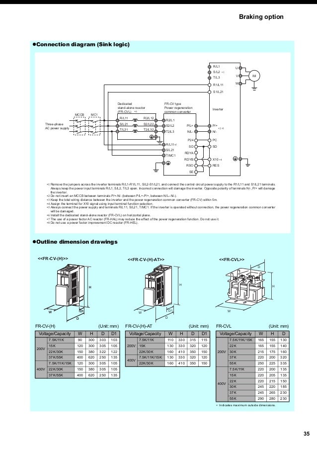
Atv320 Wiring Diagram

Vt Commodore Ignition Wiring Diagram, Complete Wiring Diagrams For Holden Commodore VT, VX, VY, VZ, VE, VF, 5.36 MB, 03:54, 32,796, John Amahle, 2018-08-01T19:37:41.000000Z, 19, Vt Commodore Ignition Wiring Diagram, to-ja-to-ty-to-my-to-nasz-swiat.blogspot.com, 1272 x 1800, jpeg, bcm pcm 12j swiat nasz, 20, vt-commodore-ignition-wiring-diagram, Anime Arts
Of units in pkg. Connection diagrams diagram with line contactor. Digital inputs wiring the logic input switch (sw1) is used to adapt the operation of the logic inputs to the technology of the programmable controller outputs. Training team confidential property of schneider electric.
• identify i/o wiring, • number of logical inputs: _____ • number of logical outputs: Altivar machine atv320 variable speed drives for asynchronous and synchronous motors programming manual 04/2018 nve41295. 2 nve41295 10/2017 the information provided in this documentation contains general descriptions and/or technical characteristics. • carefully install the wiring in accordance with the emc requirements. Atv320_installation_manual_en_nve41289_06 action_download_stroke pdf (10. 5 mb) document title date languages Of units in pkg. Connection diagrams diagram with line contactor. Digital inputs wiring the logic input switch (sw1) is used to adapt the operation of the logic inputs to the technology of the programmable controller outputs.
Pinout Altivar

Schema Electrique Bloc Alimentation Pc Pdf ~ schéma câblage et branchement de tableau electrique

Nf 320 Wiring Diagram - Wiring Diagram

Nf 320 Wiring Diagram - Wiring Diagram

ATV610C13N4 - variable speed drive ATV610 - 132 kW / 200HP - 380...415 V - IP20

How do you wire a starter switch for a Deere Model 320 6 position
Atv Wiring Diagram

Nf 320 Wiring Diagram - Wiring Diagram

ATV340D55N4E - variable speed drive - 55kW- 400V - 3 phases - ATV340 Ethernet

Nf 320 Wiring Diagram - Wiring Diagram

