Battery Isolator Solenoid Wiring Diagram

Vt Commodore Ignition Wiring Diagram, Complete Wiring Diagrams For Holden Commodore VT, VX, VY, VZ, VE, VF, 5.36 MB, 03:54, 32,796, John Amahle, 2018-08-01T19:37:41.000000Z, 19, Vt Commodore Ignition Wiring Diagram, to-ja-to-ty-to-my-to-nasz-swiat.blogspot.com, 1272 x 1800, jpeg, bcm pcm 12j swiat nasz, 20, vt-commodore-ignition-wiring-diagram, Anime Arts
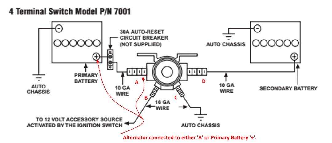
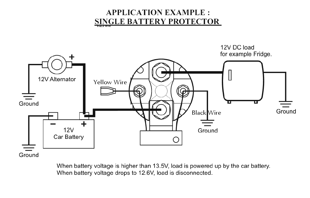
Battery rv isolator solenoid batteries wire trailer parallel tow etrailer isolation ready question adding needed. Wiring battery engine diagram switch twin hull boating truth. Wiring battery engine diagram switch twin hull boating truth. The black wire is connected to the charge solenoid chassis battery terminal which is wired to the chassis battery bank.
Connect power from the main battery to the input of the isolator. Pac 80 battery isolator wiring diagram. Reconnect these same wires to the 1 terminal of the battery isolator. The solenoid isolator uses a continuous duty solenoid to connect the auxiliary battery during certain times (like starting and charging) then disconnects when not in use. The starter solenoid wiring diagram is no more a mystery. It is very easy. If you don’t know what wires go to the starter solenoid. Here is a quick illustration. I need a simple wiring diagram to wire my winch battery isolator to be able to charge it while my 7 pin connector is hooked up and towing my trailer with my truck, wiring it from the trailer 7 pin connector.
Battery isolator Wiring Schematic | Free Wiring Diagram

34 Continuous Duty Solenoid Wiring Diagram - Wiring Diagram List
Battery Boost Wiring - iRV2 Forums
200 Amp Relay - High Current - Automotive Battery Isolator
21 Unique Dual Battery Solenoid Wiring Diagram

Redarc Solenoid Wiring Diagram - Wiring Diagram
Cole Hersee Battery Isolator Wiring Diagram - Wiring Diagram

Dual battery wiring - Ford Truck Enthusiasts Forums
Continuous duty solenoid install, replacing isolator - Electrical - Toyota Motorhome Discussion

Freightliner Starter Solenoid Wiring Diagram | hobbiesxstyle

