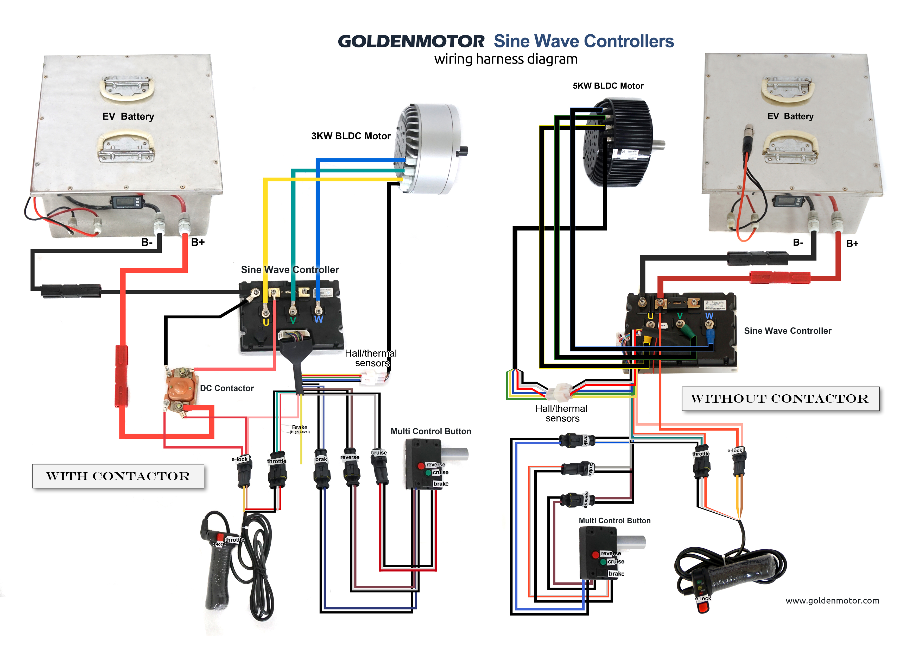
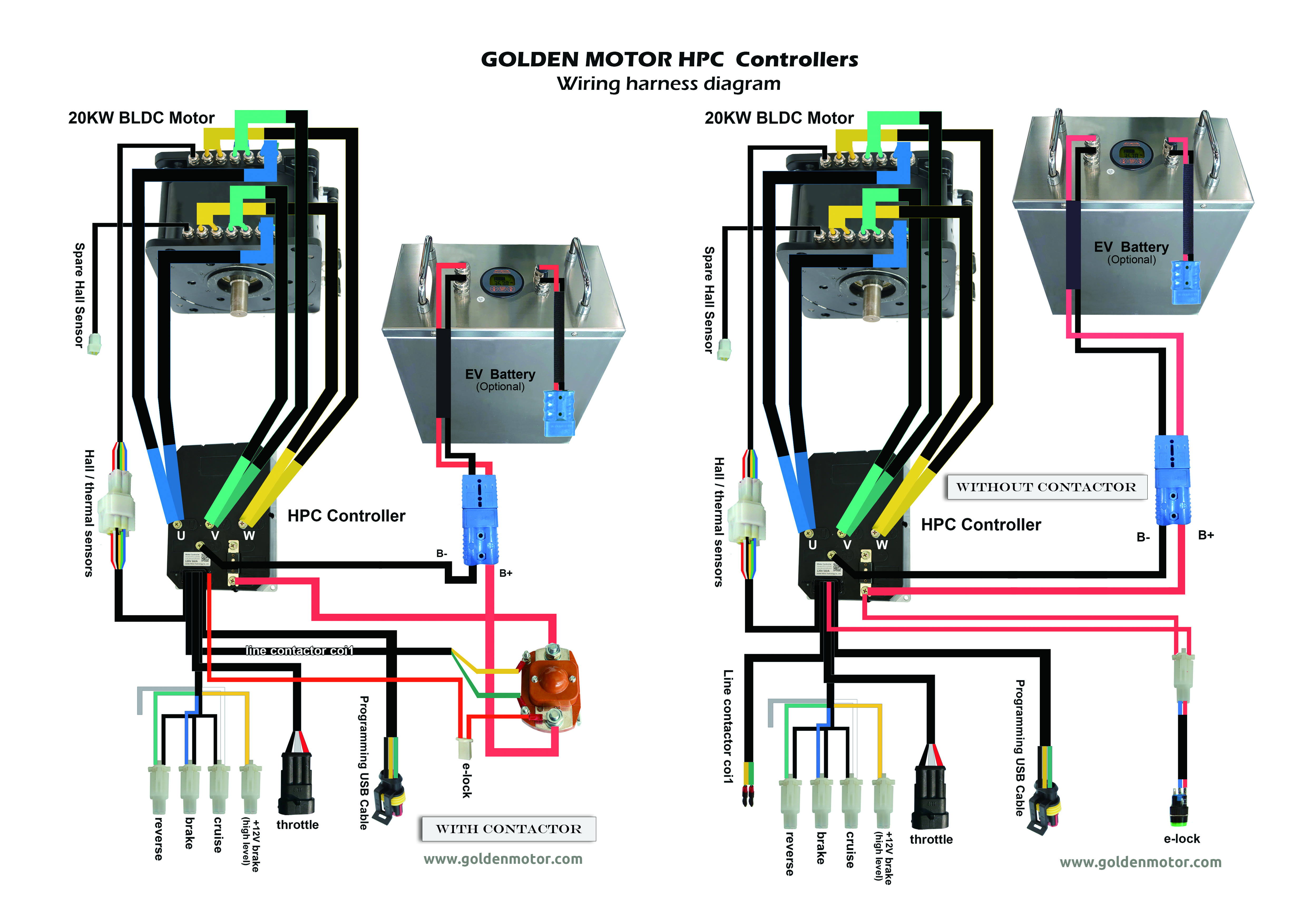
Brushless Dc Motor Controller Wiring Diagram

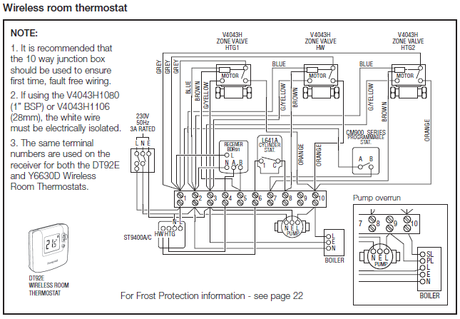
Vt Commodore Ignition Wiring Diagram, Complete Wiring Diagrams For Holden Commodore VT, VX, VY, VZ, VE, VF, 5.36 MB, 03:54, 32,796, John Amahle, 2018-08-01T19:37:41.000000Z, 19, Vt Commodore Ignition Wiring Diagram, to-ja-to-ty-to-my-to-nasz-swiat.blogspot.com, 1272 x 1800, jpeg, bcm pcm 12j swiat nasz, 20, vt-commodore-ignition-wiring-diagram, Anime Arts
The brushless motor controller schematic: So i will happy when u send me logic circuit diagrams u used thanks u so much. March 21, 2014 at 15:33. I am learning about control sensorless brushless motor dc 3 phase.
The characteristics and specification of a brushless dc. First, it carries a maximum current of 13a for 1 minute. Additionally, it has an operating voltage of 10v more or less. Lastly, it has a load current of 0. 5a. The controller of these two phase angles requires no direct exchange. There are two correct wirings for the eight leads connecting the brushless electric motor with the phase angle of 60°and the controller with the phase angle of 60°. One is forward rotation and the other is backward rotation. As to the bldc motor with the phase angle of 120. The video explains the different.
48v Brushless Motor Controller Wiring Diagram

43 Brushless Dc Motor Controller Wiring Diagram - Wiring Diagram Harness Info

48v Brushless Motor Controller Wiring Diagram
48v Brushless Motor Controller Wiring Diagram

Bldc Motor Controller Wiring Diagram | Free Wiring Diagram

48v Brushless Motor Controller Wiring Diagram

current - in order to understand bldc motors and their working principle, I read a lot on the
44 Bldc Motor Controller Wiring Diagram - Wiring Diagram Source Online

Brushless Motor Wire Diagram - Wiring Diagram Schemas

Arduino Brushless Motor Control Tutorial | ESC | BLDC - HowToMechatronics in 2020 | Arduino

